Programable Logic Controllers: VersaMaxNano
For machine and factory automation products and solutions please click on the following website: http://www.gefanuc.com/en/
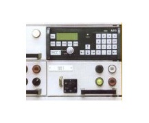
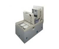
Motor Control Center (MCC) – SEV32 IntelligentMotor Control Centre – EPOS
- The ideal solution giving flexibility in design, protection and control
- Integration into a Fieldbus either through Modbus or Profibus
- EPOS makes engineering and modifying the design easier and faster
- Planned maintenance becomes a simpler task, reducing operating costs
- Modification becomes an easy operation, minimizing component change and time
- Rated operational voltage: 690v
- Rated current: Up to 5000A
- Rated insulation voltage: 1000v
- Rated short time withstand current: Up to 80kA
- Rated impulse withstand current: Up to 176kA
- Protection class to IEC 529: IP 20 to 54
- Height: 2200mm
- Depth: 600 & 1000mm
- Width: 400, 500, 600, 800 & 1000mm
- Typical form of segregation: Form 1 to 4.7
- Structure: Aluzinc
- Independent certification: KEMA
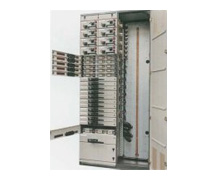
Motor Control Center (MCC) – SEV32 Motor Control Centre
- Type tested to IEC 439, IEC 947 and DIN. VDE. 660 pt 500
- Arcproof design, fully insulated bus bars and risers to maximise safety
- Fully withdraweable incomers and feeders, including comprehensive safety interlocks 2to protect both person and plant
- HSEV Fuse Switch available in either BS/DIN fuses or MCCB configurations in up 32 modules per column
- Compact design gives up to 32 x 11kW starters in a column all easy to cable, install and maintaining protection for the electrician from live connections and parts
- Fully withdrawable starters up to 280kW also Soft Starters & Variable Speed rives
- Designed for front access allowing direct mounting against a wall having total ease of use from the front for installation and maintenance
Software Support: PowerDesign 1.0
This program assists the installer and board technician when preparing and creating quotations for industrial and commercial GE electrical distribution systems: Modula Plus, Modula 630K and SEN Plus and SE Digital Power.
Key Features
- Automatic configuration (places devices automatically into the enclosures)
- Calculation screen where the customer can introduce all the cost and benefit parameters they require
- Display of the customer logo in reports
- Front and rear technical drawing views
- Export to MS office and PDF format files
- Discount management
- Net prices management
- 8 different languages
- Unique drag and drop concept to facilitate user friendliness
- Incorporation of specific or non GE devices
- Connection with ProceraPlus
- 3 different ways of selecting devices
- Copy and paste of entire cabinets as well as individual kits
- New environment with modern look and feel
- Focus on speed of configurations and accuracy of reports
- Addition of Material Quotation, a new module to create quick quotations
- Manage the modules added into every Kit
- And many more features….
Software Support: ProceraPlus v5.02
Designing, drawing, calculating and monitoring low-voltage installations in accordance with the HD384
GE is launching the new ProceraPlus® software package for designing and calculating complete low-voltage installations. ProceraPlus® is a Windows-based package,which enables the user to choose the correct security for the most appropriate distribution system, as well as related components. ProceraPlus helps to quickly and simply calculate the short-circuit resistance in each point of the installation. The program offers a perfect balance between installation costs and comfort level (preventing unwanted cuts).
ProceraPlus® can make calculations for up to 50 distribution boards, 300 circuits and maximum 6300 A. New elements in this version include:
- The option to install 6 ordinary and 1 emergency source in parallel.
- Multiple predefined end circuits such as sockets, lighting, heating, capacitor bank, engine or LV/LV transformer.
FEATURES
Concept of the installation
- In horizontal and vertical direction
Sources
- Number of supply sources: 6 ordinary + 1 emergency (up to 6300A) in parallel + standby power unit
- Earthing system: TN(-C-S), TT and IT with and without neutral
- Public distribution starting from Ik
Circuits
- Distribution board
- Terminal circuit: Motor, socket-outlet, lighting, heating, transformer LV/LV, capacitor bank (pro distribution board), miscellaneous.
Protections
- Circuit breakers for general purpose
- Residual current devices
- Safety fuses of type gG/gL, type aM + thermal engine protection
- Back-up protection and selectivity
Printing
- Dossier = collection of documents
- Document: cover page, sources, single-wire diagram (general, pro distribution board), circuit (+ characteristics), cable table, security device setting
Help Screens
- Linked to the on-screen parameters
Manual
- With full colour illustrations and explanations of the most important technical terms
Cooling
Cooling units – top/roof mounting
- Cooling unit for top-mounting : cools at source of heat
- Every unit is fitted with a fault contact
- Every unit is fitted with lifting lugs to facilitate installation
- Finish RAL 7035
- IP54 protection against the switch cabinet
- IP34 protection against the ambience
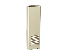
Cooling units – side and door mounting
- Cooling unit for lateral installation
- Every unit is fitted with a fault contact
- Suspension device for easy installation
- Finish RAL 7035
- IP54 protection against the switch cabinet
- IP34 protection against the ambience
Air/water cooling unit
- For vertical installation – sealed with protective edging
- Water circuit tested for 30 bar pressure
- Temperature regulated by integrated thermostat
- Finish RAL 7035
Cooling units – door/side mounting
- Easy to install with "snap in" installation
- Light weight construction
- Finish RAL 7035
Air:/water heat exchanger
- For horizontal mounting – water circuit tested for 30 bar pressure
- Sealed with protective edging
- Temperature regulated by integrated thermostat and solenoid valve
Ventilation
The electrical operating elements built into a control enclosure, such as power converters, transformers, inductance coils, contactors, relays, etc., emit dissipation heat into the surrounding air.
If this dissipation heat is not removed, it may cause the temperature inside the enclosure to exceed the temperature permissible for electrical equipment. This poses a hazard to, in particular, electronic components.
The heat must therefore be removed to avoid malfunction and, ultimately, idle time. Natural aeration (by domes, gills, etc.) is not recommended, as the risk of contamination is very high and, in addition, the degree of protection of the enclosure cannot be maintained.
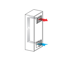
In such cases, forced aeration with appropriate built-in filters is the answer. In this system, the cooler ambient air is sucked by a fan into the lower part of the control enclosure, simultaneously filtered, and then blown into the body of the enclosure.
Here the air absorbs the dissipated heat and is then removed via an exhaust filter located in the upper part of the enclosure. An overpressure created simultaneously in the enclosure prevents dust particles penetrating any openings in the housing. Removing warm air by suction is not recommended, as the partial vacuum created within the enclosure would neutralise the dust protective effect.
Our filter fans are conform relevant CE regulations.
Contact-Voltage proof to DIN 31001. Resistance to foreign bodies and water to IP54 (EN 60529) is achieved by combining a horizontal air flow with a gasket delivered as a standard.
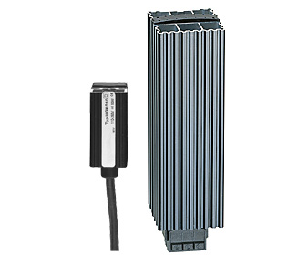
Heating
- Small heating units for enclosures are important accessories for guaranteeing operational safety of control and distribution units
- They are mainly used to prevent formation of condensation or to maintain a minimum temperature inside the enclosure, that is, a few degrees above the temperature of the surrounding air
- Energy saving
- Dynamic heating-up
- Self-regulating
- Temperature-limiting
- Quick snap-on fixing
- No maintenance
- Long endurance
- Compact housing
- In accordance with VDE 0700, IEC 60 335-1
- Fitting, push-fit onto DIN 35 mm rail (EN 50 022)
- Installation preferably at the bottom of the cabinet, at about 40 mm from the equipment itself
UC-Cabinet – Subterranean enclosures
As we share the same space with an ever increasing number of people, public areas like streets, squares and parks will be used with increasing intensity, creating a strong demand for solutions that manage to avoid obstacles at street level as much as possible.
GE Power Protection, being a major supplier of street level distribution switchboxes for telecommunications, energy and CATV distribution connectivity, has developed UC-Cabinet enclosures for this purpose. UC-Cabinet enclosures are switchboxes that are installed underground and are suitable for installing all kinds of equipment for permanent or temporary connectivity. The distinguishing characteristic of UC-Cabinet enclosures is that they can remain underground both in active and passive condition, which means that they do not constitute any obstacle whatsoever.
These UC-Cabinet enclosures can be employed, among other applications, for temporary mains hook-ups for the benefit of markets, fairs or other events. However, they are also eminently suitable for permanent connections, low voltage energy distribution, glass fibre connections for a variety of IT related applications, or for installing supporting equipment for mobile telephony.
The tops of the underground UC-Cabinet enclosures can be finished in such a way that they become an aesthetically pleasing part of their surroundings.
UC-Cabinet – The principle of the diving Bell
The principle of the UC-Cabinet enclosure is based on the same principle as the diving bell.
A diving bell is a 5-walled, hermetically sealed compartment.
Under normal conditions, the opening is at the bottom, so that in case of a rising water table the underside is closed off completely by water.
As the water table rises, the air present in the sealed unit will be compressed until an equilibrium is reached between the air pressure and the force exerted by the rising water, at which point the water will rise no further (Boyle’s Law).
Even if the UC-Cabinet enclosure becomes fully immersed in water, for example in the case of flooding, heavy rains etc. the air bubble trapped in the sealed compartment will remain large enough to prevent the plastic enclosures in which the equipment has been installed from coming into contact with water.
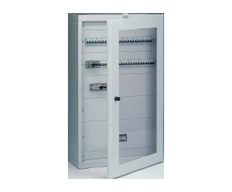
Switch board: Modula 630K
- A range of 12 enclosures equipped with a various range of functional units based on a module of 50 mm x 500 mm offering maximum possibilities to the panelboard builder
- Type tested distribution boards according to EN 60439-1
- Type tested energy distribution enclosure conforms to EN 60439-1
- LOVAG approved
- Manufactured in sheet steel and delivered in flat pack format
- Designed for 630A – 690V 40/60 Hz – 30 kA eff
- Easy wiring, due to the direct mounting of the functional units on the rear panel, used as mounting plate
- Cabinets are available as standard with protection degree IP41 and a high mechanical impact of IK08
- The application of the range makes it ideal for installation in electrical distribution systems in industrial and commercial markets
Modula 630K Features
- Delivered in kit form
- Form 1 and Form 2
- Easy wiring due to direct mounting of the functional units on the rear panel, used as a mounting plate
Protection Level
- Without door IP40 – IK07
- With plain door IP41 – IK08
- With transparent door IP41 – IK07
Materials Used
- Sheet steel coated with oven-baked epoxy paint
- Doors, side panels and roof: 1 mm thick
- Upper/bottom panels and bases: 2 mm thick
- Sendzimir zinc plated steel
- Rear panel: 1.5 mm thick
- Coupling kit: 2 mm thick
Colours
- RAL 7035: enclosure, doors and protective covers
- RAL 7024: bases